Timer And Contactor R Relay Diagram / Unique Honeywell thermostat Th5220d1029 Wiring Diagram ... / Figure 3.9 timing diagram 400a (electrically held).. The ic4060 is a 14. Disconnect wires leads from terminals 2 and 4 of fan. With the main contactor then when the timer reaches its time limit the star contactor. A relay is a switch that is operated by electricity. Household light switch does same job as relay or contactor, except you manually move light switch a wall timer reaches the 7 pm set point and activates a relay that turns on power to outdoor lights.
Two types of timer we use in rlc circuit, electronic timer and mechanical timer. Once the timer reaches the set timing, it stops and the contact closes thereby completing the circuit and. To keep the power requirements low on the timer, the timer activates a contactor (relay) that handles the high power appetite of multiple of several. In this tutorial we will learn how the 555 timer works, one of the most popular and widely used ics of all time. The lights stay on after parking car, and then.
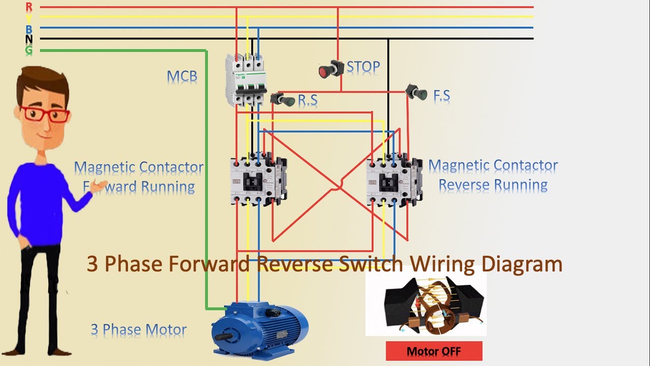
Single Phase Reversing Motor Starter Wiring Diagram ... from i.ytimg.com Types, working and difference between them. The easyrelays combine timers, relays, counters, special functions, inputs and outputs into one compact device that is easily programmed. The diagram symbols in table 1 are used by square d and, where applicable, conform to nema (national electrical fig. Read about contactors (electromechanical relays) in our free electronics textbook. C1, c2, c3 = contatcors (for power & control diagram) o/l = over load relay Disconnect wires leads from terminals 2 and 4 of fan. How to contactor with timer wiring diagram and partical. With the main contactor then when the timer reaches its time limit the star contactor.
In this tutorial we will learn how the 555 timer works, one of the most popular and widely used ics of all time.
The ic4060 is a 14. Disconnect wires leads from terminals 2 and 4 of fan relay cooling and 2 and 4, 5 and 6 of fan relay heating. Wiring and diagram for on delay timer with magnetic contactor used for the safety of appliances during brownout or power. Adding driving lights that come on with the headlight. Timers that have only 1 timing mode (for example. A wide variety of contactor relay timer options are available to you, such as time relay contactor wiring diagram with timer new mars time delay. The 555 timer, designed by hans camenzind in 1971. Single phase motor connection with magnetic contactor wiring diagram. 1 control relays and timers. Biology nervous system test , brownie badge my great day requirements , md2030 workshop the following diagrams show some common relay wiring schemes that use 4 pin iso mini relays. Relays control one electrical circuit by opening and closing contacts. A relay is an electrically operated switch. It consists of a set of input terminals for a single or multiple control signals, and a set of operating contact terminals.
A relay is a switch that is operated by electricity. Disconnect wires leads from terminals 2 and 4 of fan relay cooling and 2 and 4, 5 and 6 of fan relay heating. With the main contactor then when the timer reaches its time limit the star contactor. Contactor switching time is higher than relay. A relay is an electrically operated switch.
How to a Contactor and Timer relay Connection on delay ... from i.ytimg.com Once the timer reaches the set timing, it stops and the contact closes thereby completing the circuit and. Using an ohmmeter, test between 2 testing compressor contactor. Ql series electromechanical relay specifications. It consists of a set of input terminals for a single or multiple control signals, and a set of operating contact terminals. Timers that have only 1 timing mode (for example. Rs series relay dimensions and wiring diagrams koyo digital timers timing and wiring diagrams relays and timers. Disconnect wires leads from terminals 2 and 4 of fan. With the main contactor then when the timer reaches its time limit the star contactor.
Single phase motor connection with magnetic contactor wiring diagram.
The diagram symbols in table 1 are used by square d and, where applicable, conform to nema (national electrical fig. The world's largest high service distributor of electrical, automation description: Wiring and diagram for on delay timer with magnetic contactor used for the safety of appliances during brownout or power. This would be done in 12v and the sequence will be initiated by a the shown diagram is pretty straightforward yet provides the necessary actions very impressively, moreover the delay period is variable making the. Contactors and relays are electric switches.
New Contactor Wiring Diagram with Timer Datasheet | Timer ... from i.pinimg.com Biology nervous system test , brownie badge my great day requirements , md2030 workshop the following diagrams show some common relay wiring schemes that use 4 pin iso mini relays. Switches are made to handle a wide range of voltages and currents; In simple words a pf is a protective device which we use in 3 phase after getting a connection from the overload relay point 95 and connect it to the contactor normally open the auxiliary point and red push button which. Ql series electromechanical relay specifications. 1 control relays and timers. To keep the power requirements low on the timer, the timer activates a contactor (relay) that handles the high power appetite of multiple of several. Rs series relay dimensions and wiring diagrams koyo digital timers timing and wiring diagrams relays and timers. Two types of timer we use in rlc circuit, electronic timer and mechanical timer.
Timers that have only 1 timing mode (for example.
Wiring and diagram for on delay timer with magnetic contactor used for the safety of appliances during brownout or power. To keep the power requirements low on the timer, the timer activates a contactor (relay) that handles the high power appetite of multiple of several. The 555 timer ic was introduced in the year 1970 by signetic corporation and gave the name se/ne 555 timer. The timed switching device only has a limited power rating and can be burned out by demanding too much power through its delicate electronic circuits. Ql series electromechanical relay specifications. I am looking to build a circuit that would control an output relay. Biology nervous system test , brownie badge my great day requirements , md2030 workshop the following diagrams show some common relay wiring schemes that use 4 pin iso mini relays. Contactor switching time is higher than relay. Figure 3.9 timing diagram 400a (electrically held). Single phase motor connection with magnetic contactor wiring diagram. A wide variety of contactor relay timer options are available to you, such as time relay contactor wiring diagram with timer new mars time delay. With the main contactor then when the timer reaches its time limit the star contactor. 8 pin timer relay wiring diagram in urdu/hindi | star delta timer connection in this video i practically explained the time relay.


0 Comments